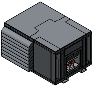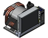


Installation location:
Self-contained units MUST be placed inside the air conditioned area of the vessel – NEVER let them suck bacteria laden bilge fumes or possibly the carbon monoxide tainted air from an engine room. We recommend every vessel with a generator has high-quality CO (carbon monoxide) detectors installed. The units must also recirculate the air conditioned air of the boat, not hot/humid fresh air. Think of an air conditioner as a powerful vacuum cleaner sucking air out of whatever compartment it is in and blowing this air through the ductwork. Every pass of air over the evaporator will drop the temperature about 18-22°F- no unit can take in 95% humidity, 95°F air and discharge it at a dry 55°F.
Typical installation locations are under a settee, under a bunk, at the floor or ceiling of a closet, under the V berth, on a shelf at the ceiling level, etc. Like all HVAC equipment, it is good form to place the slowly dissolving chlorine tablets such as “Kontrol” in the wet drain pan to combat mold/mildew etc. a few times a year. You can install a unit in an engine room or lazarette if you box it off so that the return air comes ONLY from the inside of the vessel – it must be airtight from the engine room or liner of the boat.
The most common installation mistake is to leave even a small opening such as a 1″ crack that is open to the liner of the boat – you will end up mixing for example 50% bilge air with the air conditioned air – the unit will never catch up and sweat profusely from the humidity – the compartment must be airtight from the bilge or liner.
Discharge Air Ducting:
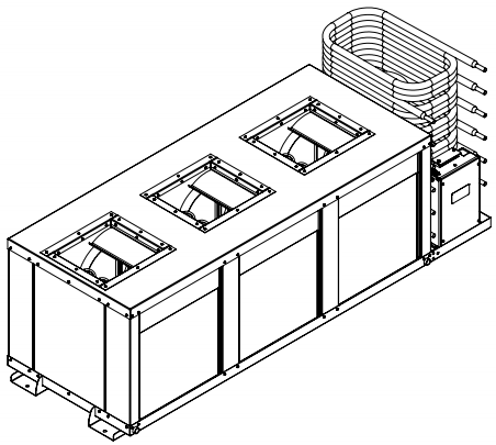
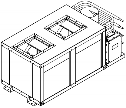
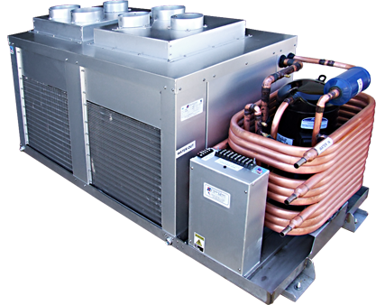
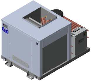
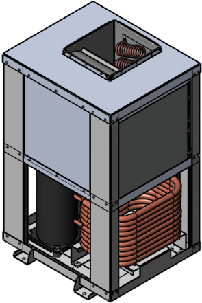
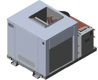
To greatly simplify the discharge ducting we supply aluminum plenums that bolt directly onto the blower flange that have the correct number of 4″ collars on them for the size of the unit. The 4″ flexible ducting attaches to these collars with a plastic wire-tie and terminates at the 4″ discharge grills. Do not block off any ducts – this will reduce the airflow over the evaporator which may cause the unit to cycle off and on via the freeze control switch.
The most desirable location for our grills is on a bulkhead near the ceiling. In fact, if you have trouble running the ducting you can place the discharge grills right next to each other and simply point them in different directions. The cold air will bounce off of the headliner and gently drop down into the room, and our blowers are powerful enough to de-stratify the air in both the heat and cool mode if properly sized for the application. The discharge air will normally travel about 8-10′, so of course you will have to run a duct to the V for example if the unit is in the main salon and you want to cool the V berth.
Common mistake: Make sure you get the cold/dry discharge air away from the return air intake of the a/c. If you place your unit in the V for example, don’t install a discharge grill in the V because the V is relatively small and may be 70° when the main salon is 85°, causing the compressor to cycle off on its’ freeze control switch. We are working with approximately 20° temperature differentials: return air = 75°(24C), discharge air = 55°(13C), refrigerant = 35°(2C). To ascertain if you have properly ducted your discharge system, check the air temperature of the air at the return grill – it should be the same as the room temperature where the thermostat is located.
Because our units are so powerful for their size, we do not supply variable speed fans, however, you will not be bothered at all by the fan noise – we even insulate our blower motors – these units are very quiet.
If you design your own ducting system, do not have excessive runs of ducting or restrict the air flow return. If inadequate air is passed over the evaporator, the unit will develop frost on the evaporator and will eventually ice up unless it is equipped with a freeze control, whereby it will cycle on and off. Our units are designed to bring the air temperature down to about 70°F – if you try to attain a lower temperature you will either develop a freeze up or cycle on the freeze control.
Return Air Ducting:
There is no need for return air ducting – these units are like vacuum cleaners, sucking air from whatever compartment they are in and blowing the cooled or heated air through the discharge duct-work system. If you use our pre-designed ducting system you will be assured of having the correct amount of air flow and air velocity to successfully de-stratify the air in a properly sized application without having excessive noise or uncomfortable drafts.
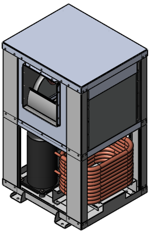
The blower motor and rotary compressors are air cooled and do get warm, therefore it’s good form to have the return air travel over these components in route to the evaporator. There is no need to have the evaporator up against the return air grill, in fact, it’s better to have the opposite – make sure the evaporator has at least 2-3″ of space from a bulkhead.
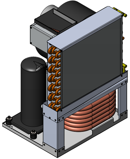
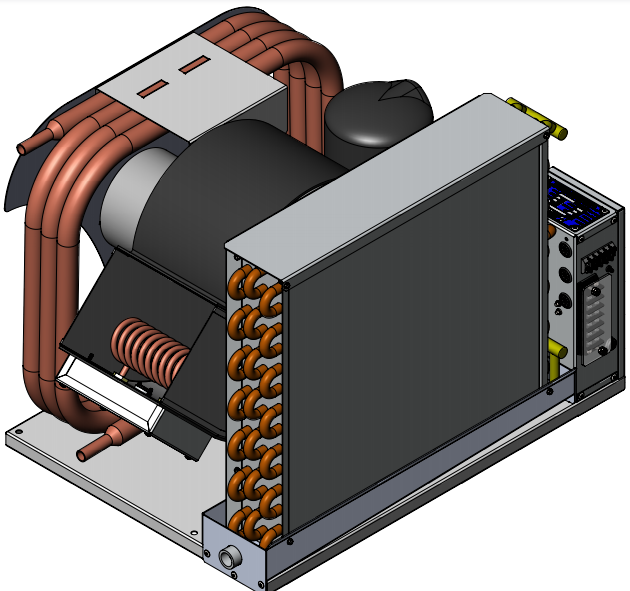
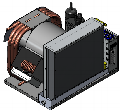
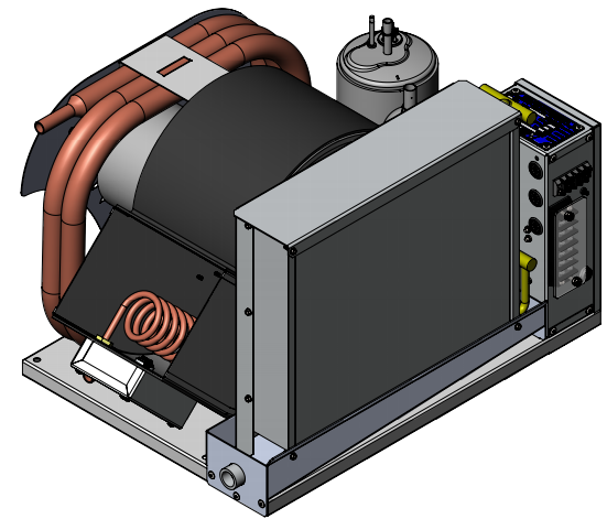
We manufacture vertical or side discharge units – although it is possible to change this after production it is difficult to do so and we don’t recommend it.
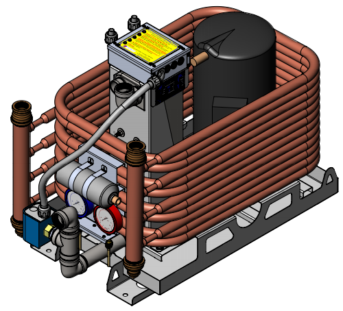
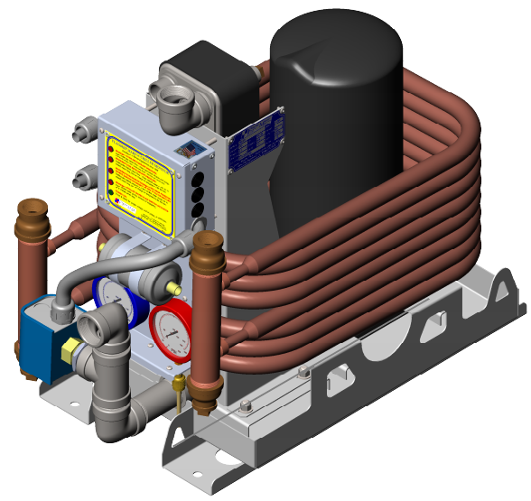
Plumbing:
The intake through hull should be as low as possible in the water in a location that is always underwater and not exposed to the backwash of the propellers whereby air bubbles could be ingested. Almost every marine air conditioning pump is a flooded volute pump and must be mounted below the waterline. For boats that are in dry storage, you may install a T fitting at the discharge of the pump with one line running to a vertical location with a valve for releasing the back pressure to simplify priming.
Frequently you can “T” off of a head intake, however we don’t recommend having the a/c share a through hull fitting with any other pump such as the engine or generator because of the hazard of the more powerful impeller pump sucking air backward through the a/c rather than water from the through-hull fitting, possibly overheating and damaging your equipment. The units’ discharge through hull fitting should be between 4″ and 8″ above the waterline – if below 4″ it would have to be treated as a “below the waterline” through hull and would be required to have a valve – above 8″ the noise of the running water may be bothersome.
Care should be taken to avoid crimping the suction line. If long runs of plumbing are required or if the unit is placed well above the waterline you may end up with too much head pressure necessitating a higher volume pump. We have a variety of pumps in stock, and the charge to increase the GPM capacity is nominal – see our pump page.
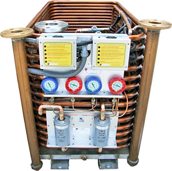
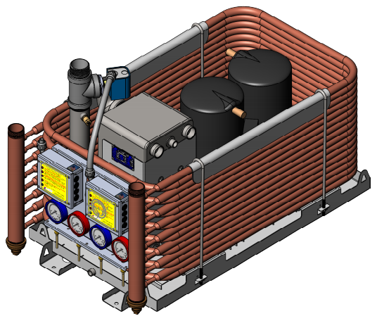
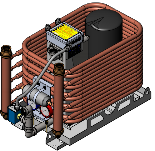
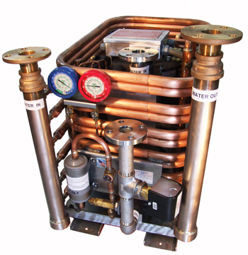
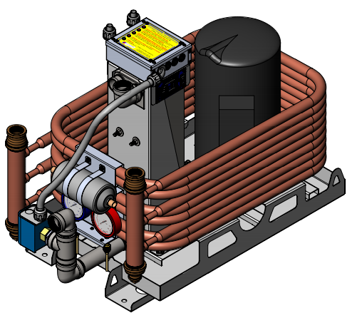
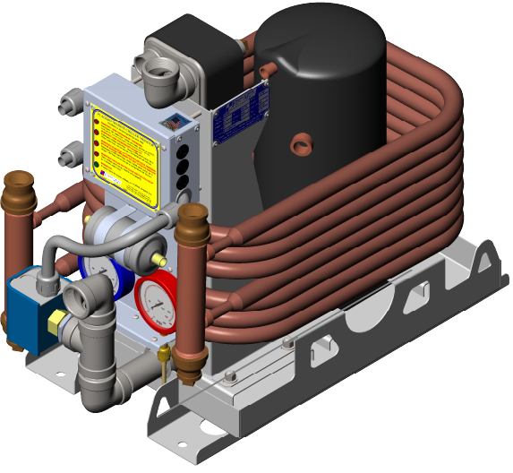
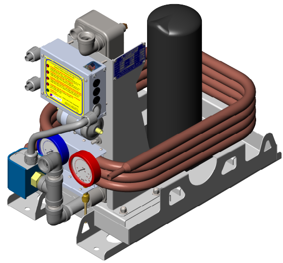
The seawater requirements for cooling our equipment is about 200 gallons/hour/ton of air conditioning(12,000BTUs= one ton) at a maximum temperature of 100°F. The only metal the salt water touches is the inside of a 90/10 CuNi condensing tube which is inside a copper shell. We do not use a serrated, knurled or enhanced tube to increase the surface area because we find our slick inner tube to be less prone to trap debris and much more durable – we make up for this loss of surface area by extending the length of the condensing tube ensuring long-term trouble-free operation.
All of our condensing tubes are 5/8″OD, and for systems of up to about three tons of A/C (36,000 BTUs), a single 3/4″ intake through hull set up is adequate – larger systems may need a 1″ or larger, depending on the total GPH requirements.
In multiple unit installations, we often suggest using one large pump with a pump relay box whereby each unit has a 24 volt wire returning to the pump relay box (usually mounted by the pump), and if any one of the units engage, the pump will supply water to all of the units.
Depending on the number of units and pump size, we often run one 1″ supply line from the pump from which 5/8″ T’s supply individual units. The sea water discharge from each unit can be individual by each unit or tied together into one or more discharge through hull fittings.
The condensate drain line should never be connected to the raw water discharge line- if there were a blockage in the discharge line, the raw water pump would pump raw water back into the drain pan and ultimately into the boat causing a sinking hazard.
The condensate drain line is a gravity line and the highest point of this line will determine the water level in the condensate pan. A common mistake is to have the condensate line run a couple of feet at the same level of the chassis – if there is any section even 1″ above the bottom of the chassis, you will have excessive water in the drain pan.
Under normal operating conditions, the condenser (the copper tube within a tube on the unit) should be warm to the touch – if you cannot feel any heat in the condenser whatsoever when the compressor is running, you have too much cold water passing through it. This is only a problem in some areas where the water temperature is 40°F and the air temperature is 90°F. This can be remedied by installing a gate valve on the supply line at the unit to throttle down the water flow. Remember to never restrict the SUCTION side of a centrifugal pump, conversely, there is no harm restricting the DISCHARGE side of a centrifugal pump.
If the condenser is too hot to hold your hand on constantly, you are not getting enough cooling water. This is not a very scientific way of determining water flow but it works. Most of our units have manually resettable high pressure switches on the condenser, whereby if the unit is operated without enough cooling water and the refrigerant pressure on the high side reaches the limit, the switch will activate, shutting down the compressor until it is manually reset by pushing in the button.
Electrical:
All of our units are pre-wired onto two clearly marked terminal blocks. We recommend the use of GFI (ground fault interrupt) breakers for any high voltage equipment near water, and always use stranded wire – never use solid core wire on any vessel because the motion of the vessel may eventually cause a failure and can be a serious fire hazard.
Be sure to use the proper size wire for our equipment. Undersized wire or poor dock/ship connections will result in a voltage drop that may damage the equipment and be a fire hazard. Use a minimum 12 gauge power supply wire – never use 14 gauge for even our smallest units if wired 115 volt. Be sure the breaker capacity is less than the current capability of the wire – for example, with a high-quality #12 wire @120VAC, don’t use a breaker of more than 30 amps. Use quality wire – cheap #12 wire may be rated at less than 30 amps, typically the larger number of strands and the higher the voltage capability of the wire determines its capacity – use wire rated at a minimum 600V.
Many marinas have inadequate wiring -we suggest you test the dock line voltage during peak loads -it may be 120 volts on a cool weekday morning and 90 volts on a hot weekend afternoon. The high voltage block has three connections for the power supply and three connections for the pump – don’t mix them up. This terminal block is clearly marked, however, if you wish to confirm which is which, the heavier gauge wires are the power in and the lighter gauge wires are the pump output terminals. With 120V systems, the black wire is your line (L), which goes to the circuit breaker, the white wire is your neutral (N), which goes to the neutral buss bar, and the green wire is always ground (G), which goes to your ground buss bar. With 230V systems, there is usually no neutral, (the white wire) and there are two lines, one black(L1) and one red(L2), both of which must be on a dual terminal 230V breaker.
The low voltage terminal block connects to the digital control – we use the HVAC industry standard – red, white, green, yellow color code – any domestic thermostat will operate any of our equipment and you will never have to helicopter in a rocket scientist to figure out our digital control, in fact, one can cross all of these wires except the white for cool or all of the wires except the yellow for heat. The 24 volts for the digital control output is produced by an internal transformer in the a/c unit.
The internal electronics of our digital control are powered by two AA batteries, therefore these delicate components are not subject to line voltage spikes, etc. To replace these batteries simply remove the four #1 Phillips head screws on the faceplate to access the batteries. You will find a reset-able breaker on all of our equipment – safety is our primary concern and we strive to make our equipment as foolproof as possible.
Our unique and time tested heating element does not “burn” the air – it never gets red hot because it is in the direct discharge of the blower motor – these elements are actually mounted inside the blower chamber and have a controlling temperature sensor that affords one a “post purge” feature (the fan continues to run until the element is less than 110°F after the element is de-energized) and two high voltage, high temperature safety shut off temperature sensors wired in series.
With a Flagship Marine a/c there is no need for the troublesome reversing valves and component wear and tear for heat – the many benefits of electric heat far outweigh the slightly more efficient reverse cycle heating systems, and you will find the reliability and simplicity of a straight cool unit to be a great advantage. Please visit our “Electric Heat” web page.
The use of rotary or scroll compressors has greatly reduced the problems with “start upsurge”- and we have further reduced this surge by installing as standard equipment, hard start capacitors on all units over 12,000BTU’s(scroll compressors excluded – inherently negligible start up surge). Typically, the dinosaur-like piston compressor has a 350% startup surge, the newer rotary compressors a 150% start-up surge (without the hard start capacitor- about 120% with.) and the scroll compressors a mere 110% start-up surge.
Miscellaneous:
Our freeze controls will prevent the compressor from starting if the refrigerant temperature is below 38°F, therefore don’t think there is a problem with the unit if you test the unit in February when it is cold – it will not start. Once the return air temperature is below 70°F, or if you have excessively cold raw water in the spring, it is a normal function for the compressor to cycle off for a few minutes occasionally to prevent ice from forming on the evaporator.
Never Check The Freon Pressure:
There are no hoses, seals or gaskets to leak or “migrate” freon molecules into the environment – this is a totally closed system that is of a “critical charge” type, using capillary tubes – even the small amount of freon lost by connecting and disconnecting the gauges may affect the unit’s performance. There is no need to ever check this pressure for if it were to be low on charge there would have to be a leak and a need for the unit to be repaired on the bench – this is an almost non-existent situation.
Important Maintenance Concerns
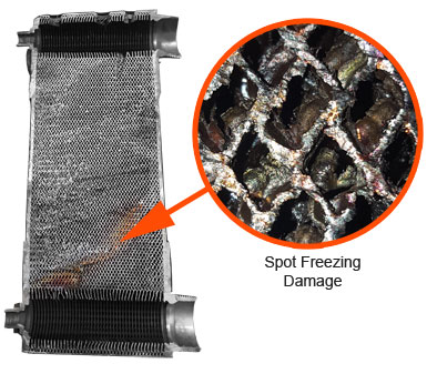
“Spot Freezing” can result in a catastrophic chiller failure. We STRONGLY suggest a 16-20 mesh strainer is installed on the return chilled water line before the evaporator and a 30-40% propylene glycol (non-toxic) solution is incorporated.
If there is debris in the chilled water, even a small section of blockage in the evaporator can result in “spot freezing” which can rupture the evaporator. There is no safety device that will prevent this because it is a small spot that ruptures, therefore the low refrigerant pressure and low temperature protective devices will never be triggered. The only preventative measures to prevent such failures are an antifreeze solution in combination with a filter that will prevent solids from reaching the evaporator.
Brazed Plate Heat Exchanger Cleaning Recommendations
We recommend that you clean the heat exchanger by reverse flushing it with a mild organic acid solution. In other words, have the acid solution enter the heat exchanger through what is normally the water outlet. The flow rate for the flushing should be greater than the normal operating flow rate of the heat exchanger (2 x if possible).
When using a solution other than water, always use it according to instructions and check with the supplier that it is compatible with the materials in the heat exchanger. The units are constructed of AISI 316L Stainless Steel with AISI 304L connections. The units are brazed with pure copper.
Once the cleaning operation has been completed, you may want to also run a solution (1 – 2 %) of either sodium hydroxide (NaOH) or sodium bicarbonate (NaHCO3) through the heat exchanger. This solution will neutralize any residual acid that may have remained after flushing the heat exchanger with water. The heat exchanger should also be thoroughly flushed with water after using the neutralizing solution.